Render Backend
VDS uses the wgpu graphics API to render all visualizations. Shaders are written in the WebGPU Shading Language also known as WGSL and can be translated to various native graphics APIs like Vulkan, DirectX or Metal. This is why VDS supports so many different plattforms listed on Supported Plattforms.
wgpu Coordinate System
Since all graphics pipelines are written with wgpu and WGSL, the underlying coordinate system is the one from WebGPU, which is identical to the coordinate system of DirectX and Metal.
Note: All custom shaders must be compliant with the WebGPU coordinate system, no matter which graphic API backend is used by the plattform. All coordinates will be transformed by wgpu to match the plattform graphics API coordinate system. So do not assume the coordinate system of for example Vulkan when VDS uses Vulkan as render backend.
Normalized device coordinate system
Normalized device coordinates use a left-handed coordinate system and map to positions in the viewport. These coordinates are independent of viewport size. The bottom-left corner is at (-1.0, -1.0, z). Positive-z values point away from the camera (“into the screen”) and are clipped between 0.0 and 1.0.
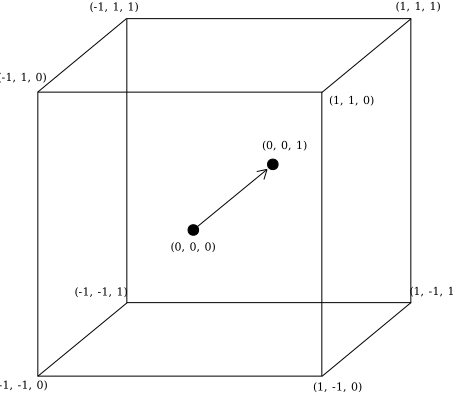 |
|---|
| Normalized device coordinate system |
Framebuffer coordinate system
Framebuffer coordinates adress pixels in the framebuffer and have two dimensions (x, y). Those dimensions are not normalized, so each pixel extends 1 unit in x and y dimensions. The top-left corner is at (0, 0).
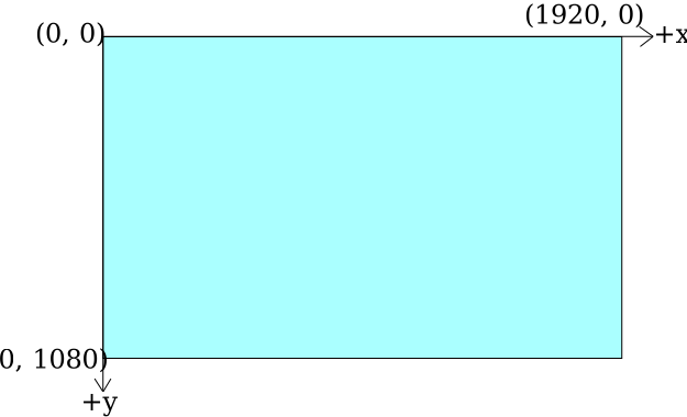 |
|---|
| Framebuffer coordinate system |
2D Texture Coordinates
2D textures us a normalized coordinate system. The origin of a 2D texture is a the top-left corner with +Y facing down. Sometimes uv coordinates are used to describe a texture coordinate, where (u, v) is equal to (x, y).
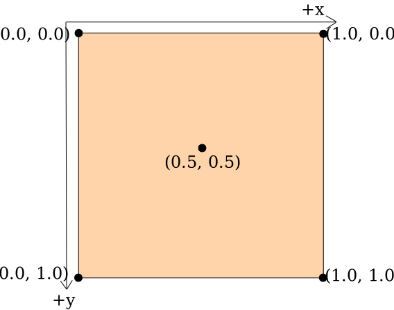 |
|---|
| 2D texture coordinates |
3D Texture Coordinates
3D textures us a normalized coordinate system. The origin of a 3D texture is a the top-left-front corner with +Y facing down and +Z facing back, similiar to DirectX 11. Sometimes uvw coordinates are used to describe a texture coordinate, where (u, v, w) is equal to (x, y, z).
Differnces to other APIs like OpenGL and Vulkan
Other graphics APIs like OpenGL and Vulkan use different coordinate systems. This section aims to highlight the differences between those coordinate systems to mitigate misunderstandings.
WebGPU & DirectX & Metal
NDC: +Y is up. Point (-1, -1) is at the bottom left corner.
Framebuffer coordinates: +Y is down. Origin (0, 0) is at the top left corner.
2D Texture coordinates: +Y is down. Origin (0, 0) is at the top left corner.
OpenGL & OpenGL ES & WebGL
NDC: +Y is up. Point (-1, -1) is at the bottom left corner.
Framebuffer coordinates: +Y is up. Origin (0, 0) is at the bottom left corner.
2D Texture coordinates: +Y is up. Origin (0, 0) is at the bottom left corner.
Vulkan
NDC: +Y is down. Point (-1, -1) is at the top left corner.
Framebuffer coordinates: +Y is down. Origin (0, 0) is at the bottom left corner.
2D Texture coordinates: +Y is up. Origin (0, 0) is at the bottom left corner.
3D Volume Scaling
VDS only supports uniform and non-uniform volume data that is represented as a regular grid of voxels. This means, that each that the distance between all voxels must be identical on the same axis.
Not supported a irregular or non-linear distance between voxels along either axis.
During the import process, the bounding box of the volume data is normalized. This means, that aspect ratio of the volume is applied to the bounding box and afterwards the volume gets scaled in a way, that the longest side of the bounding box equals a length of 1.0.
Z-Values and Depth Buffer
Z-Values represent the distance of a pixel from the camera in projection coordinates. The near clipping plane is set to 0.1 and the far clipping plane is set to 10.0 which results in a in far-plane/near-plane ratio of 100. At a ratio of 100, 90 percent of the precision range is spent on the first 10 percent of the depth range (D3D Docs). This is suitable for all volume renderers of VDS, since the bounding box of the volume data is always normalized due to the 3D Volume Scaling.
The Depth Buffer contains depth values between 0.0 and 1.0, where 0.0 is the closest distance and 1.0 is the furthest distance. All Z-Values get mapped from the range of the near-plane - far-plane to the range of 0.0 - 1.0 respectively. VDS uses wgpu::TextureFormat::Depth32Float for the depth buffer.
Depth Buffer and Ray Marching
The depth of each pixel is set to first sample point the ray that exceeds the threshold value.
For non-translusent visualization methods like “First Hit” the depth value is set accordingly to the visible surface shown on the screen.
For translusent visualisation methods like “Accumulate” the depth value is set accordingly to the first visible layer shown on the screen, even if it extremely translucent and barly visible. This is due to the fact that depth values are assigned to a pixel, while the pixel color value is calculated by accumulating all the samples in the raymarching ray.